System P-70. W systemie FF budowano hale o jednej tylko rozpiętości 18,0 m; natomiast w systemie P-70 były budowane hale jednonawowe i wielonawowe o rozpiętościach od 6,0 do 24,0 m, ze zmianą rozpiętości co 3,0 m. Dla hal o rozpiętościach 12,0; 15,0 i 18,0 m przyjęto w kierunku podłużnym rozstaw słupów 6,0 i 12,0 m.
Podobnie jak w systemie FF, ustrój konstrukcyjny hal jedno- i wielonawowych składa się ze:
a) słupów jedno- i dwugałęziowych,
b) dźwigarów strunobetonowych,
c) dźwigarów kablobetonowych,
d) płyt dachowych żelbetowych,
e) płyt dachowych sprężonych,
f) belek podsuwnicowych żelbetowych, z betonu sprężonego i stalowych,
g) elementów ściennych.
Słupy w realizowanych budynkach systemowych są rozwiązywane indywidualnie. Kielich stopy fundamentowej powinien mieć głębokość większą o co najmniej 20% od większego wymiaru poprzecznego słupa.
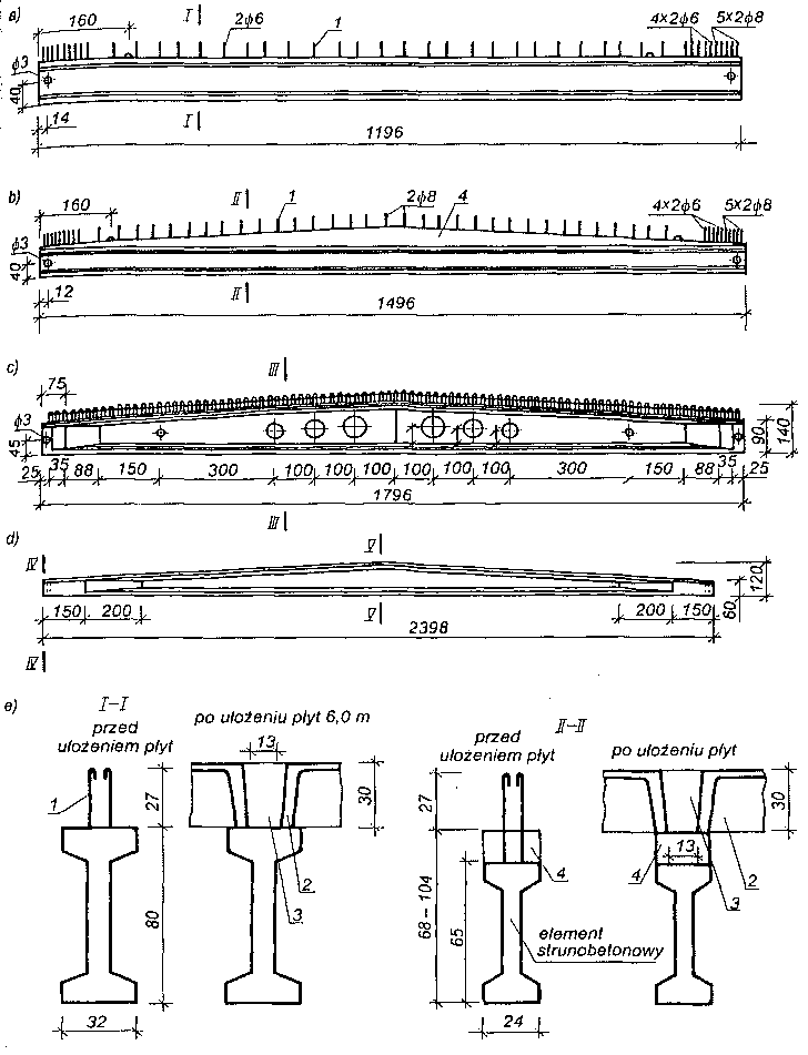 Dźwigary strunobetonowe: a) dźwigar o pasach równoległych, SB-l-80/12, b) dźwigar o pasach równoległych z betonem spadkowym SBn-I-65/15, c) dźwigar dwuspadkowy SBSFF-90/18, d) dźwigar SBL-24, e) przekroje poprzeczne ze szczegółami oparcia płyt dachowych;
1 — strzemiona wystające z dźwigarów, 2 — płyta żebrowa, 3 — nadbeton między płytami, B15, 4 — nadbeton spadkowy B35.
Na rysunku przedstawiono dźwigary strunobetonowe stosowane na przekrycia hal. Dźwigary strunobetonowe produkowane są o stałej i zmiennej wysokości o rozpiętościach 9,0; 12,0; 15,0; 18,0 i 24,0 m, natomiast dźwigary kablobetonowe z pasem górnym w kształcie łuku produkowane są o rozpiętości 18,0; 21,0 i 24,0 m. W systemie P-70 przewidziano stosowanie płyt dachowych żelbetowych i sprężonych. Istnieje kilka odmian płyt dachowych żelbetowych, a mianowicie; z żebrami poprzecznymi na długości płyty, bez żeber, z otworami na świetliki oraz przyokapowe i podświetlikowe. Długość płyt żelbetowych wynosi 587 cm, szerokość 119 i 149 cm, a wysokość 30 cm.
Na przekrycia hal są stosowane płyty sprężone płaskie z systemu FF oraz płyta łupinowa Pt-12p.
W skład belek podsuwnicowych systemu P-70 wchodzą: belki żelbetowe o rozpiętości 6 m i wysokości 40, 60 i 80 cm, z betonu sprężonego i rozpiętości 6 m i wysokości 60 i 90 cm oraz o rozpiętości 12 m i wysokości 90 i 120 cm, a także stalowe o wysokości od 83 cm do 130 cm.
W systemie P-70 rozróżnia się płyty ścienne bez izolacji i z izolacją termiczną. Płyty produkowano w wielu odmianach i kształtach. Przekroje ścian podłużnych hali w systemie P-70 przedstawiono na rysunku.
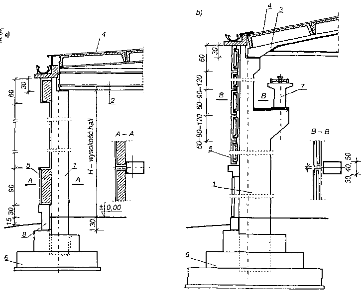 Przekroje ścian podłużnych: a) przekrój hali bez suwnic, b) z suwnicą; 1 — słup, 2 — dźwigar strunobetonowy, 3 — dźwigar kablobetonowy, 4 — płyty dachowe, 5 — płyta ścienna, 6 — stopa fundamentowa, 7 — belka podsuwnicowa, 8 — belka podwalinowa.