Złącza systemu W-70
 Złącza poziome ścian wewnętrznych i stropów (W-70): a) oparcie stropów na ścianie nośnej, b) oparcie stropów na ścianie usztywniającej; 1 — elementy ścian wewnętrznych, 2 — płyty stropowe, 3 — śruba rektyfikacyjna, 4 — beton, 5 — zaprawa cementowa, 6 — pętle stalowe, 7 — klamry stalowe, 8 — zbrojenie w postaci drabinki, 9 — wysunięte „łapy”.
Złącza systemu W-70
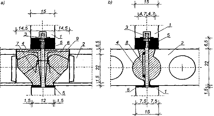
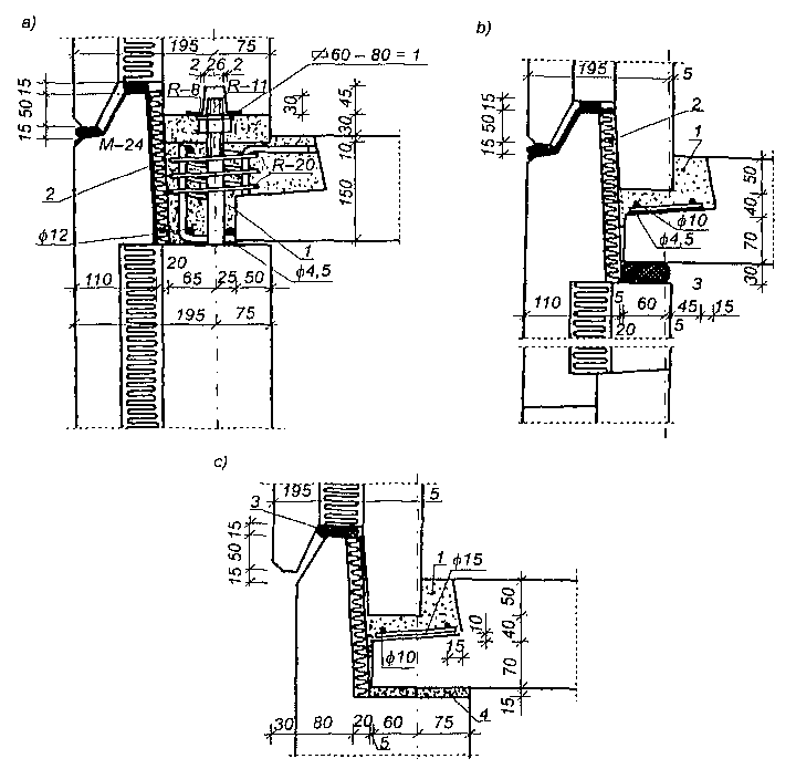
Na rysunku pokazano połączenie płyt stropowych ze ścianą nośną wewnętrzną. Na złączach tych, na odcinku równym grubości stropu, podstawowa część sił pionowych przenoszona była za pośrednictwem betonu wieńca, z niewielkim tylko udziałem zakończeń płyt stropowych. Osiągało się to przez oparcie stropów w złączu za pośrednictwem wysuniętych wsporników stanowiących przedłużenie żeber płyt stropowych. Wsporniki te ułatwiały jednocześnie zastosowanie wymuszonego montażu wewnętrznych ścian konstrukcyjnych na śrubach rektyfikacyjnych, które przechodziły przez wieniec w przestrzeniach między wspornikami. Szerokość wsporników w miejscach styku ze ścianą wynosiła 9 cm, a długość oparcia wsporników na ścianie 6,5 cm.
Płyty stropowe układało się na ścianie za pośrednictwem warstwy zaprawy o grubości 1,5 cm. Płyta ścienna wyższej kondygnacji opierała się na wieńcu za pośrednictwem warstwy zaprawy o grubości 3,5 cm, umieszczonej w poziomej spoinie przez podbijanie. Podczas podbijania zaprawy płyta ścienna górnej kondygnacji spoczywała na nakrętkach śrub rektyfikacyjnych wystających z płyty ściennej kondygnacji dolnej. Po stwardnieniu zaprawy, nakrętki odkręcało się nieco, tak aby obciążenie przekazywało się na wieniec tylko przez warstwę podbitej zaprawy.
Na rysunku a ściany są ustawione prostopadle do płyt stropowych, a na rys. b — równolegle.
Obrzeża ścian miały wycięcia — dybie na wysokości, dzięki czemu uzyskiwano lepsze zespolenie na przenoszenie sił stycznych występujących w złączach.
 Złącza poziome ścian nośnych zewnętrznych keramzytobetonowych (W-70): a) w poziomie kondygnacji powtarzalnej, b) w poziomie stropu nad ostatnią kondygnacją, c) w poziomie stropu kondygnacji przy ustawieniu ścian równolegle do stropu; 1 — ściana zewnętrzna, 2 — ściana wewnętrzna, 3 — płyta stropowa, 4 — beton wypełniający, 5 — zbrojenie wystające z płyt, 6 — zbrojenie złącza, 7 — śruba rektyfikacyjna, 8 — zaprawa cementowa, 9 — styropian grubości 3 cm, 10 — ścianka poddasza, 11 — ścianka ażurowa poddasza podtrzymującego płyty dachowe, 12 — płyta dachowa, 13 — uszczelnienie, 14 — okapnik z blachy, 15 — wkładka elastyczna.
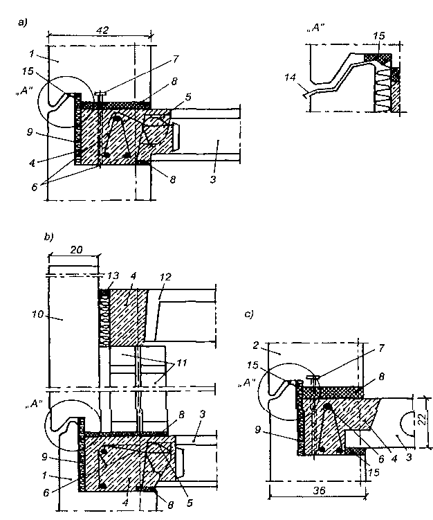
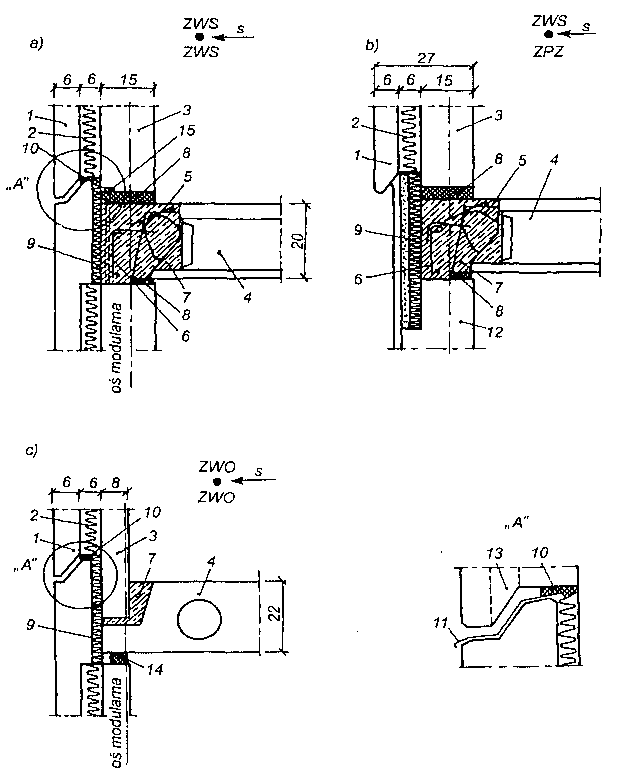 Złącza poziome ścian zewnętrznych wielowarstwowych (W-70): a) w poziomie stropu kondygnacji powtarzalnej, b) w poziomie stropu nad piwnicą, c) w ścianie osłonowej w poziomie stropu kondygnacji powtarzalnej; 1 — warstwa fakturowa, 2 — warstwa izolacyjna ze styropianu, 3 — warstwa konstrukcyjna, 4 — element stropowy, 5 — pętla wypuszczona z płyty stropowej, 6 — zbrojenie złącza, 7 — beton wypełniający, 8 — zaprawa cementowa, 9 — wkładka ze styropianu grubości 3 cm, 10 — wałek z polocelu, 11 — okapnik z blachy, 12 — monolityczna ściana piwnicy, 13 — kanał dekompresji, 14 — wkładka elastyczna z polocelu, 15 — śruba rektyfikacyjna.
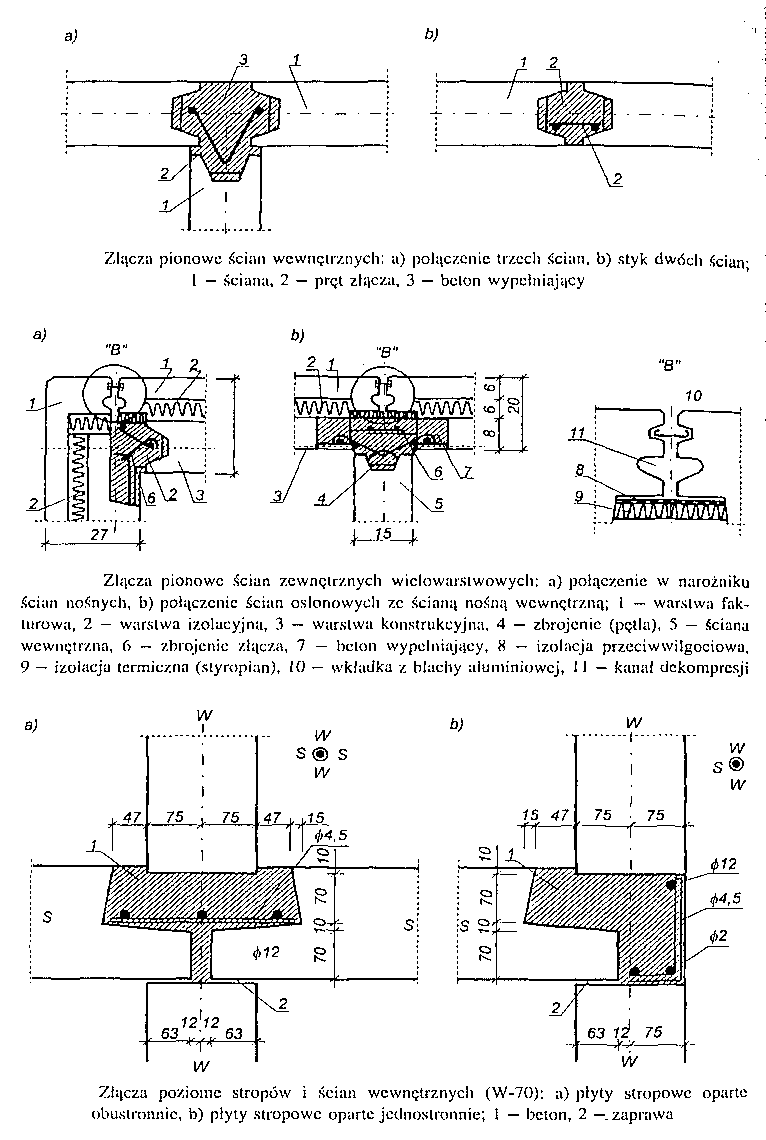
 Złącza poziome ścian zewnętrznych: a) ściana nośna, b) złącze ściany na poziomie stropu, kondygnacji powtarzalnej, c) złącze ściany na poziomie stropu piwnicy; 1 — beton, 2 — styropian, 3 — neopren lub poliuretan, 4 — zaprawa.