Hale żelbetowe monolityczne
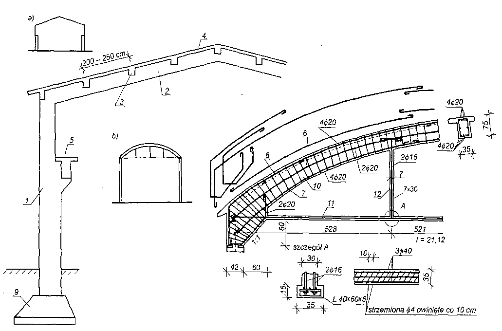 Hale żelbetowe monolityczne: a) z ryglem załamanym, b) z ryglem łukowym, c) szczegół zbrojenia tygla załamanego, d) przegubowe połączenie słupa i stopy; 1 — słup, 2 — rygiel, 3 — żebro, 4 — płyta, 5 — belka podsuwnicowa, 6 — zbrojenie montażowe, 7 – zbrojenie główne dolne, 8 — zbrojenie główne górne, 9 – stopa, 10 – łuk, 11 – ściąg, 12- wieszak.
Na rysunku przedstawiono przekroje hal żelbetowych monolitycznych o ustrojach nośnych typu tradycyjnego, które są wykonywane coraz rzadziej.
Ustrój nośny tych hal składa się z:
a) fundamentów,
b) ram o ryglach prostych, załamanych lub łukowych,
c) płyty dachowej opartej na żebrach,
d) belek podsuwnicowych.
Rozpiętość hal monolitycznych o ustrojach ramowych nie przekracza zwykle 20 m, a rozstawy slupów w kierunku podłużnym hali — 9 m. Większe rozpiętości, do ok. 100 m, osiąga się stosując konstrukcje łukowe (rozporowe).
Ramy z ryglem prostym lub załamanym rozstawia się w odstępach ok. 6 m. Na ryglach opierają się żebra w rozstawie ok. 2,0-2,5 m, na których spoczywa płyta dachowa o grubości 6-7 cm.
W halach, w których stosuje się transport suwnicowy (podparty) slupy najczęściej mają przekrój zmienny na wysokości. Ponieważ z belek podsuwnicowych działają duże siły pionowe na słup, w związku z tym belkę opiera się bezpośrednio na słupie, aby zmniejszyć mimośrodowe działanie siły. Przy lekkich suwnicach belki podsuwnicowe opiera się na wsporniku wystającym ze słupa.
Podobnie jak rygle proste czy załamane, również rygle łukowe mogą być połączone ze słupem sztywnym węzłem. Na rysunku przedstawiono konstrukcję ramy, w której rygiel (łuk) jest połączony ze słupem przegubowo, a siłę rozporową (rozciągającą) przejmuje ściąg stalowy, który jest podwieszony do łuku, aby nie zwisał.
Zamiast ram z ryglami łukowymi, które przenoszą obciążenie z dachu, są stosowane sklepienia łukowe ceramiczno-żelbetowe i żelbetowe ze ściągami rozstawionymi w odstępach ok. 3,0 m. Rozpiętość tego rodzaju sklepień przekracza niekiedy 20 m. Strzałka łuku wynosi 1/8—1/5 rozpiętości l.
Grubość sklepień żelbetowych w zworniku wynosi 6—12 cm, natomiast przy wezgłowiach 12-25 cm. Zbrojenie z prętów o średnicy 6-10 mm układa się w środkowej części jednostronnie, przy wezgłowiach dwustronnie. W kierunku podłużnym stosuje się pręty rozdzielcze i przeciwskurczowe o średnicy 6 mm. Tego rodzaju sklepienia stosuje się wtedy, gdy na przekrycie działają obciążenia ciągłe równomierne lub niewielkie symetryczne siły skupione.
Sklepienia ceramiczno-żelbetowe wykonuje się podobnie jak stropy gęstoże-browe ceramiczno-żelbetowe. Istnieje wiele odmian pustaków ceramicznych, które są stosowane do budowy sklepień. Pręty zbrojenia o średnicy 12-16 mm są układane w żeberkach między pustakami u góry i na dole.
Przekrycia cienkościenne mają małą grubość mierzoną prostopadle do ich powierzchni w porównaniu do ich długości, szerokości i wysokości. Konstrukcje te mogą mieć kształt:
a) powłok jednokrzywiznowych,
b) powłok dwukrzywiznowych,
c) fałd lub tarczownic.
Do najczęściej stosowanych powłok o pojedynczej krzywiźnie należą powłoki translacyjne, które powstają przez przesunięcie równoległe krzywej (tworzącej) wzdłuż linii prostej. Przykładem mogą tu być powłoki walcowe o kształcie koła, elipsy, paraboli itp.
W celu zwiększenia sztywności powłoki o większej rozpiętości wykonuje się przepony poprzeczne pełne lub w postaci żeber wystających od góry lub od dołu. Rozstaw przepon wynosi 6—12 m.